Digital Resonator
Over the past few months I have been exploring some ideas that started sprouting in my head over 10 years ago, to design and implement a real-time dynamic model of tonal perception, i.e. not using the ubiquitous FFT… but for now I will just share some fun results I have been able to achieve with a digital oscillator model.
The first milestone in my exploration is to build a simple digital resonator, a dynamic system that resonates with a specific frequency if present in an input signal (such as that captured by a microphone), i.e. that naturally oscillates with greater amplitude at a given frequency, than at other frequencies.
Note that there is a large body of work related to bulding real-time oscillators for synthesizing periodic signals (both in hardware and in software), but my objective is to analyze a signal (or a periodic component thereof).
I will not cover all the technical details here, but simply outline the main ideas behind my design.
-
a resonator is characterized by its (resonant) frequency (inverse of its period duration) and the shape of its periodic signal (could be any periodic function, in this case a sine wave)
-
because we operate in the digital world, the sampling rate (inverse of sample duration) of the input signal is an important parameter as taking it into account affords some significant optimizations in the design of the system and in the calculations involved in computing the interaction between the input signal and the amplitude of the resonator. Those also come with some limitations that are out of scope for this post.
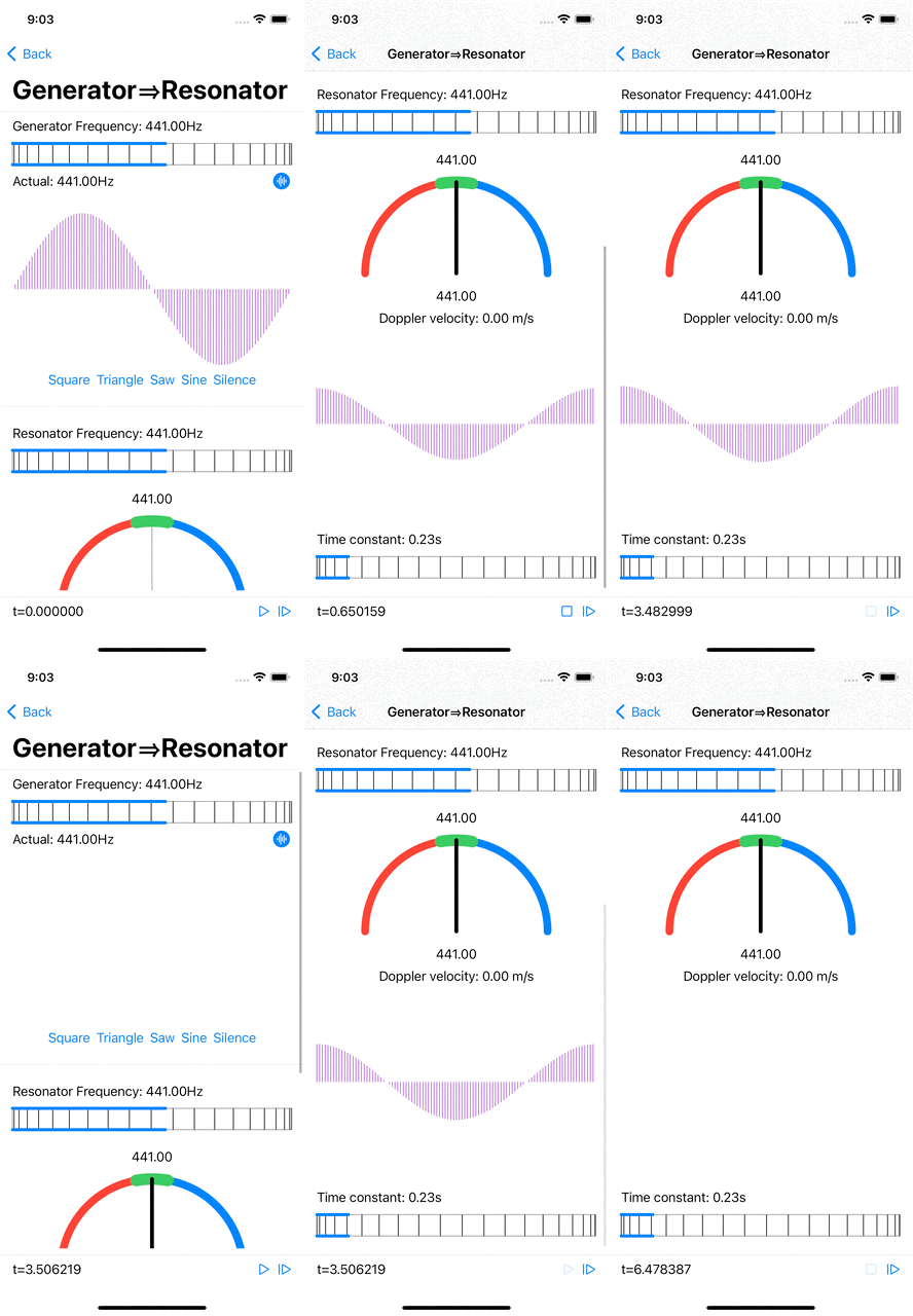
The digital resonator has a persistent state consisting of current amplitude and phase; its state gets updated at each tick of the clock, driven by the sampling rate of the input signal.
-
coupling: the contribution of each input sample to the oscillator’s amplitude is modulated by the waveform value at the current phase of the oscillator. As a result, contribution will be consistently maximal if the input signal contains a component that has the same frequency as the resonant frequency of the oscillator, provided the two are in phase. It is therefore necessary to maintain an array of oscillation amplitudes, for all (or at least several) possible phases, so that the contribution of any component at (or near) the resonant frequency will be captured independently of its phase relative to the resonator’s phase.
-
persistence: each input sample contributes to the amplitude of the system (for each phase) subject to a low-pass filter. As a result, under a 0 contribution, the system’s amplitude decays exponentially to 0 over time and under a non zero contribution the amplitude of the system increases following a sigmoid curve. Both aspects are modulated by a time constant which characterizes the responsiveness of the system. Over time, the contribution of any component at (or near) the resonant frequency will result in a higher accumulated amplitude, while the sporadic contributions of other frequencies will result in lower amplitudes.
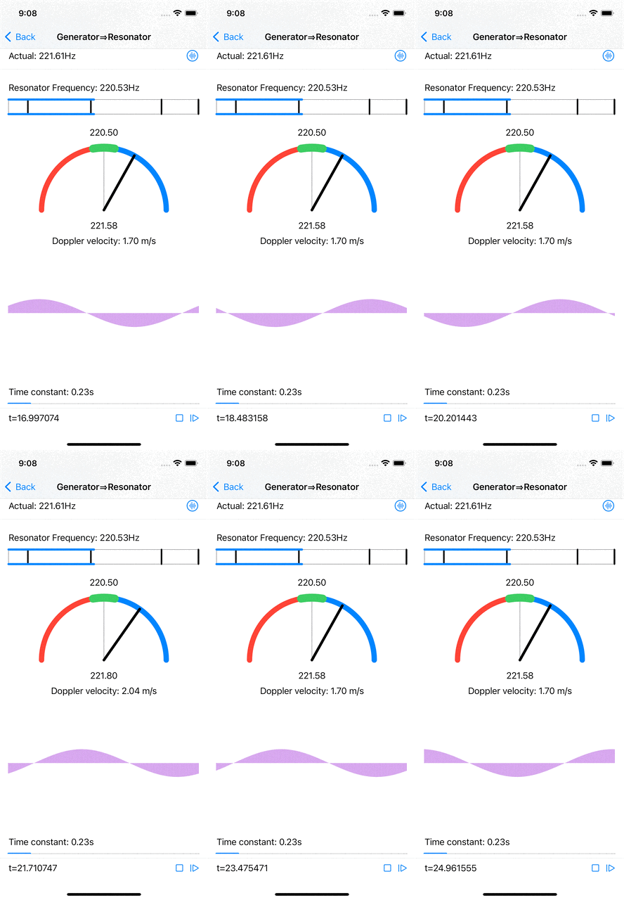
When the input signal has a frequency that is near (but not quite equal to) the resonator’s frequency, the resonator’s amplitudes do increase, less than when the signal’s frequency is spot on, and the maximal amplitude phase position is constantly shifting at a rate that is proportional to the difference in wavelength between the signal’s frequency and the resonant frequency. Computing the actual signal frequency from this shift is relatively straightforward.

|
| Near resonant frequency estimation and Doppler velocity computation. |
Furthermore, if the signal source (emitting a fixed frequency) and the “observer” (microphone feeding the resonator) are moving with respect to each other, the frequency observed by the resonator shifts according to the Doppler effect. A simple computation gives the relative velocity from the frequency shift.
But all this is worth a real world demonstration, so here is a short video…
